Providing feedback
The development of v1 of catalight took over a year. While that was a tremendous learning opportunity, the length of time means there are undoubtedly details left out from this documentation that may be crucial for first time users. Please feel free to reach out to the authors with questions, and we strongly encourage feedback on the documentation. A lot of work went into developing this project, and we want other labs to benefit from this effort and do more productive research! The original authors self learned Python while developing this project. There very well may be aspects of the project that could be improved, so please reach out of fork our Github project if you see any other areas for improvement. Your questions/feedback are not only welcome, but encouraged!
If an issue occurs while you are using the system, please open an issue on the GitHub page! This helps other users not repeat common mistakes or issues and will hopefully serve as an easy way for the future community to collaborate on improving the toolbox!
Developing equipment drivers
Catalight was built with modularity in mind. We do not want to make a code project that only allows the automation of a single lab setup! That being said, its not feasible to create a universal code package that is both user friendly and compatible with all equipment immediately. Drivers for specific pieces of equipment need to be written for users hoping to use other equipment types. Our Equipment Specific Guides section is meant to serve as both instructions for users attempting to connect the exact hardware we utilize in our lab and to serve as examples for users developing new equipment drivers.
- We ask that users developing new hardware
fork/branch our Github to eventually merge improvements to the main project,
provide manuals for equipment within the manuals/”specific_equipment_folder” directory for the new piece of equipment developed,
write a Equipment Specific Guides to help other users utilize your code, and
write your specific driver utilizing the same function names as comparable equipment that has already been developed (see Areas for future development for more thoughts on how abstract classes could be created to aid this process).
An excellent example of a flexible automated lab design can be found in the LightLab package. catalight was developed by novice programmers to be (a) more specific in scope than LightLab and (b) utilize existing Python APIs in place of developing VISA-based drivers for equipment. The trade off is that catalight is a less flexible codebase that we hope is more user friendly for researchers working on photocatalysis experiment specifically, where as LightLab is a flexible project that seems best suited for optical characterization labs.
My equipment doesn’t have a Python API
This is a tough situation and some additional programming will be required! Two approaches for this situation include (1) connecting with the equipment by interfacing with the providers software system and (2) writing low level or VISA communication interfaces, for example, by using pySerial/pyVISA.
Our SRI GC connection is an example of approach 1. There is no Python interface supported by the equipment developer or by found on PyPi or Github (that we could find). Fortunately, the equipment developer does supply a programming interface to their control software, but it is not written specifically for Python. We were able to connect to this using the “.NET infrastructure” which is a way to reuse code across multiple languages via something called “Common Language Runtime” and python.NET. If you’ve never heard of this, neither did we! Thankfully, this can look pretty simple in practice. See our SRI GC specific guide for more details on how this works.
If the producer of your equipment does not provide a Python-specific programming interface to your equipment or its software (if it has software), you may need to interface with your equipment via some communication protocol, like VISA. Some examples of this includes The pywatlow package and Brendan Sweeny’s write up on how he created it, the alicat package which uses pySerial to control MFCs, and the LightLab project which generalizes the development of VISA connections to lab equipment. Often, equipment without software or an existing API will have a programmer manual describing how to use serial/GPIB/VISA communication commands.
Ideally, users that need to develop their own communication interfaces through some read/write commands via pySerial, pyVISA, and the like can write their python driver in a seperate package, publish it, and import it into the catalight package. This is the method we chose for integrating the NKT system into catalight (nkt_tools package), rather than writing the communication code directly in catalight. It is much easier for users to use tools with more human readable commands like alicat.MassFlowController.set_flow() wrapping over the signals communication. Ease of use is exactly why we choose to use packages like alicat and pywatlow in the first place!!
Creating new experiment types
In this section, I’ll describe the addition of the NKT system into the catalight package.
Connection with the equipment:
Each piece of equipment brought into the Catalight system needs to have communication independently developed. Communicating with various pieces of hardware in a abstract and generalized way is beyond the scope of the package. Instead, users are encouraged to develop their own packages to enable hardware connection, and import those packages into Catalight for further integration with the remainder of the “virtual lab space”.
In the case of the NKT system, this was accomplished utilizing the NKT Photonics provided software development kit. This connection was established in a stan Support for an NKT laser and the Varia tunable emission system is provided through a standalone package, nkt_tools, which is installed as a requirement of the catalight package. Further details of the hardware connection can be found in the NKT Fianium/Extreme + Varia System section of this guide and the nkt_tools documentation.
Integration to Catalight:
The connection between the computer and the hardware is done within its own package. This simplifies catalight by adding some modularity, and I strongly advise that developers adding new instruments to catalight develop the communications within a seperate package.
The computer to hardware communication should be its own package. Integration into Catalight should be handled as a module within the catalight.equipment subpackage.
Altering the Experiment object
Once the nkt submodule has been written, the new equipment needs to be added to the Experiment class. This is telling the catalight system how to utilize the new equipment inside of a physical experiment. The exact procedure for implementation of a new piece of equipment will vary depending on the nature or the device. For example, the implmentation of a data acquisition device, like an FTIR or thermal camera, may only include adding an optional line that tells the device to begin collection (and where to store that data file). In the case of the NKT system, implementation involves introducting a new type of experimental procedure all together, the wavelength sweep. This section will go step by step through the additions that were made to the source code when the NKT system was first introduced, as a tutorial for future developers seeking to add their own components.
The Experiment._expt_list attribute is a non-public parameter which contains the available experiment types. The user does not/should not need to directly interface with this item. It is used to tell the system the available types of experiments, unit to use, variables to alter, and provide a central location for making alterations to these parameters in future iterations of the code.
To add a new experimental procedure, we add it to the _expt_list attribute:

This new experimental procedure will need to utilize a new experimental parameter “wavelength”. This attribute needs to be added to the experiment class in two location (1) a non-public attribute altered and accessed by the backend code and (2) a public facing property that the user interacts with. The public facing property adds some type and format checking to help ensure the user is providing inputs in the correct format.
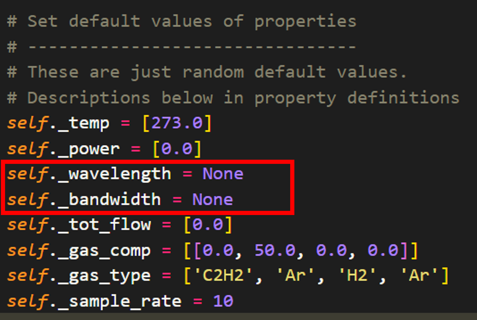
The non-public attributes are defined in one location within the class. We simply add this parameter prefoxed with “_” to hide it from the user. Here I also introduce the “_bandwidth” non-public attribute as well to allow to user to set the bandwidth of a tunable laser to a custom value for each experiment. Note that both of these parameter need to be handled with some flexibility in mind as certain hardware configurations will not be compatible with the concepts of wavelengths and bandwidths.
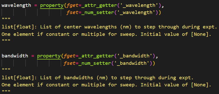
After adding the non-public attributes for wavelength and bandwidth, the user facing properties need to be created. I have written specific string and number setter functions for properties within the Experiment class. This is done so that format checking can be performed in a central location. For example, all number variables (e.g. temperature, power, wavelength) need to be provided as a list of float to the backend code. Rather than define a condition for each property, I define a “_num_setter” function that handles basic type checking. Additional conditions should be added using if statements within the _num_setter/_str_setter methods if property specfic format checking is desired.
For the wavelength and bandwidth properties, I keep things simple:
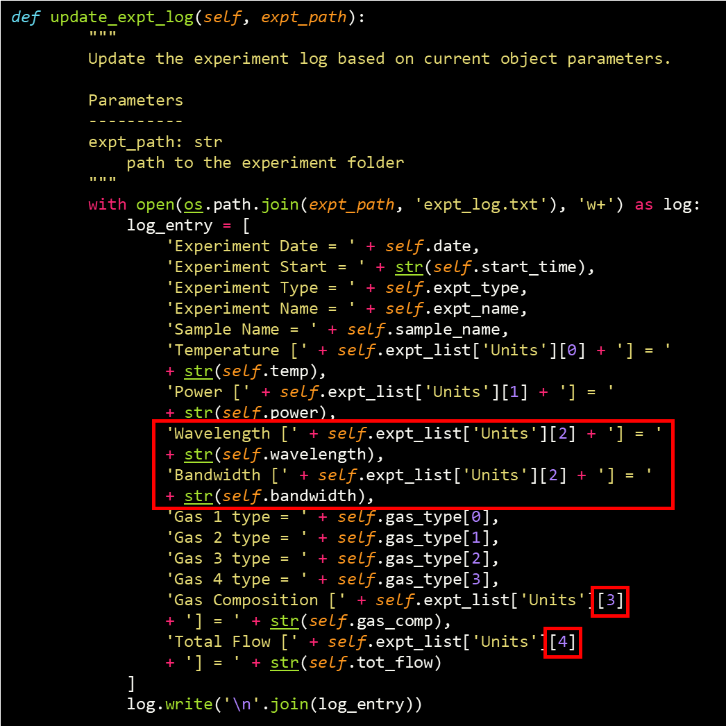
Next, the log read/write functions are updated to include the wavelength and bandwidth parameters as well. The write method (Experiment.update_expt_log) needs slight modification now that the Experiment._expt_list attribute has been modified. New lines have been written to instruct the code to write out the new parameters, but the number-based indexing of the units has been rearranged with the new addition. In the future, it would be preferred to not use number-based indexing to avoid this type of rewrite.
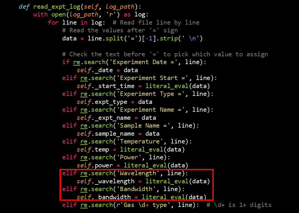
The read method (Experiment.update_expt_log) is a bit simpler to update as it reads in properties based on the line name:
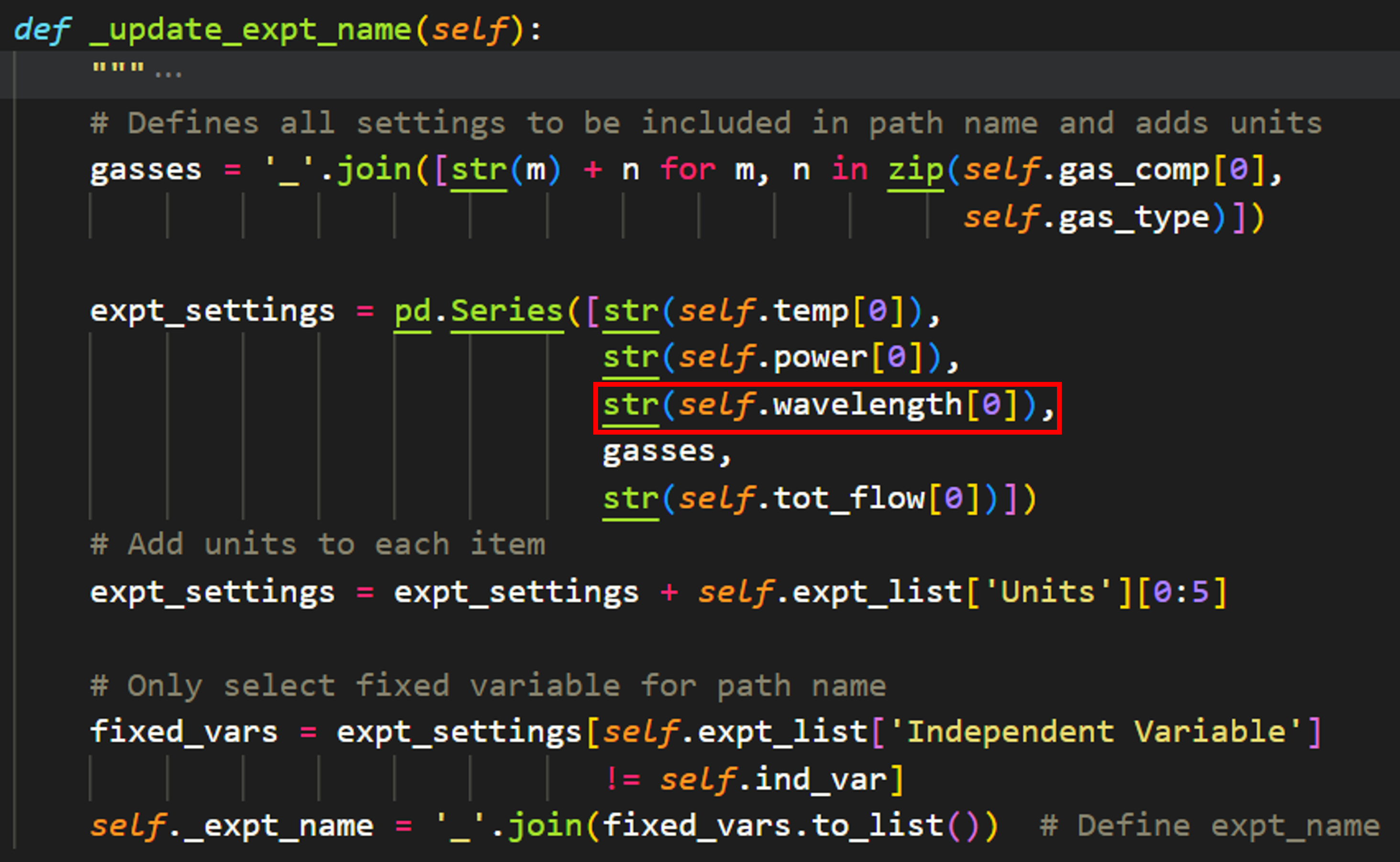
The Experiment.expt_name attribute is automatically set by the code using the fixed parameters of the experiment (thought this may change in the future now that expt_log files are implemented). This method is updated to include wavelength as well:
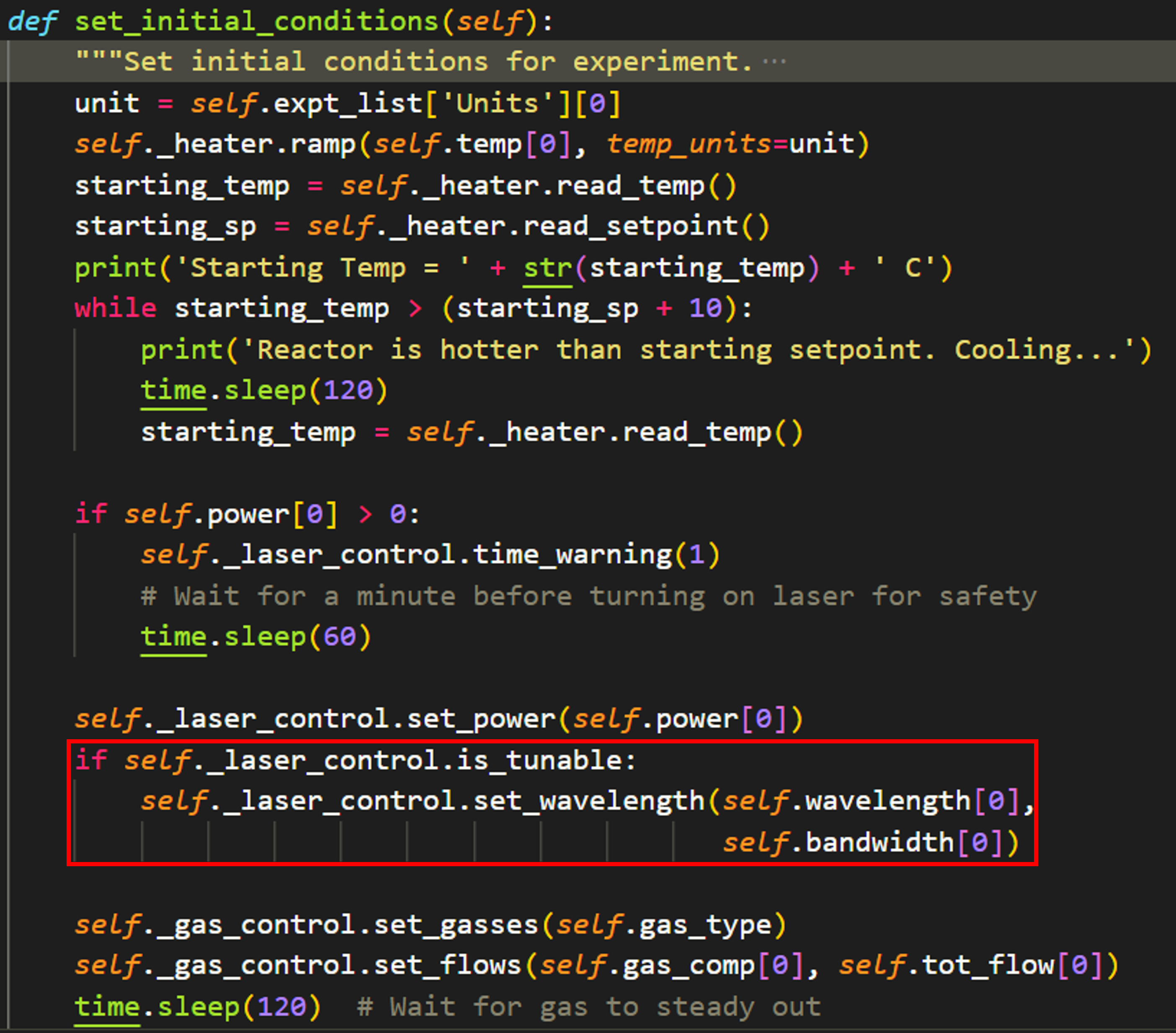
Finally, the most important changes come in the implementation of the device for the actual experiment. When the Experiment.run_experiment method is called, it first makes a call to Experiment.set_initial_conditions. This method sets all of the fixed parameters for the experiment. To implement wavelength control, I introduced a new class attribute for light sources, “is_tunable”. The code will now check whether the given light source is tunable and sets the wavelength and bandwidth accordingly.
Note
In this iteration, “None” will be passed if the user does not provide a bandwidth. This will cause an error for the NKT_system, which is desirable as it forces the user to fully define the experiment. Other systems (i.e. a tunable, fixed-bandwidth laser) will need to consider this behavior carefully)
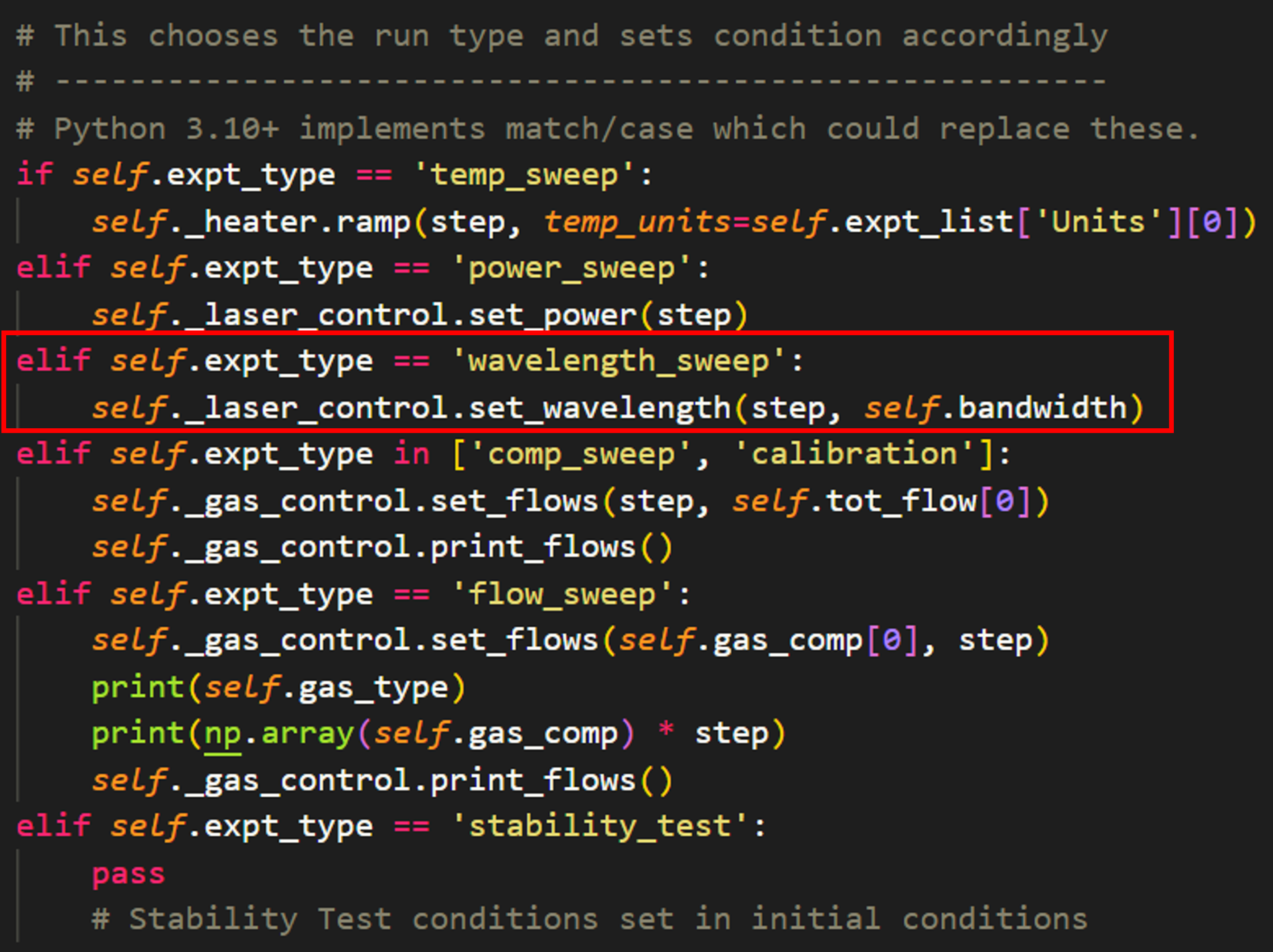
At last, the experimental procedure is defined. Within Experiment.run_experiment, there is a series of if/else statements that set the conditions for each step of the given experiment accordingly. All that needs to be added is a new elif statement for the new experiment type, then the user enters the desired method to update this experimental condition. The most important thing to consider here is that future devices need to use the same nomenclature for an identical parameter. For example, a new laser class “tunable_diode” needs to have the methods “tunable_diode.set_wavelength” and “tunable_diode.set_power” in order to be compatible with the Experiment class methods. Consistent naming maximizing modularity and reusability!
Making changes to the GUI
Function
To create new static widget, we recommend using the QtDesigner application and opening the catalight.gui_components.reactorUI.ui file. Any custom widgets added to the GUI can be inserted to the catalight.gui_components folder and promoted within QtDesigner. In the current state, all static widgets were created in this way when used within catalight.catalight_GUI and the code inside of this module connection all of the functionality of the GUI window and its components. Remember, the main purpose of the GUI is to help the user create experiment objects and “run a study”. Experimental functionality should be added to the Experiment class. New widgets should help fill attributes of the Experiment class or other classes that need to be developed in the future. A second, but major function of the GUI is to directly control hardware. Future development should allow users to choose and utilize any equipment within the GUI.
Style
catalight.gui_components.style_guide is a subpackage accessible when catalight is downloaded as a repository from the GitHub page. Within this folder is two image files and a folder containing QSS templates. The “icon.svg” and “drawing.svg” files can be replaced with the file of your choice, provided your match the filename exactly. This should replace the catalight icon and D-Lab logos within the GUI directly, without any code changes. To use alternate file types, you’ll need to utilize QT Designer (or edit the ui file - not recommended) to change the image resource path.
The QSS sheet was downloaded an lightly modified from the QSS Stock website. You can edit this file for wide-spread style changes to the GUI appearance, or enter your own QSS style sheet and insert it to the GUI by editing the path inside the catalight.catalight_GUI.setup_style() function.
Areas for future development
Design is an iterative process. The catalight project has already been updated several times going into the deployment of v1.0.0, but there is always room for improvement. Below is a laundry list of improvements that can be added to future versions of the package.
The current iteration of the system has been designed with modularity in mind, but additional improvements could be made to enable more seamless use by a variety of groups with different hardware configurations. This will become increasingly important as users develop their own equipment classes.
Better methods need to be developed to allow users to configure specific hardware with minimal coding while maximizing compatibility with the rest of the package.
For example, an abstract “GasSystem” class could be created with standardized class method names compatible with the rest of the package, then a specific “AlicatGasSystem” class can be initialized that subclasses the abstract class and decorates the class methods to make them compatible with the specific hardware used by a particular lab. In other words, the methods of every gas system should behave identically on the surface, while the actual implementation should change for each specific hardware setup. AlicatGasSystem.set_flow() needs to behave the same as a hypothetical BronkhorstGasSystem.set_flow()
This would ideally be managed in a single location, such as a configuration file, that a new user could edit once in order to make the system compatible with their hardware. Ideally no other code components would need to be edited. This configuration file could allow the user to change between “AlicatGasSystem” or “BronkhorstGasSystem”. If class abstraction is implemented correctly, the rest the code package will continue working as intended.
The LightLab package is an excellent example of flexible lab configuration and could be a very helpful reference for development in this area. In particular, future development should look into their implementation of “essentialMethods” attribute for abstract drivers and type checking in their DriverMeta class. Their tutorial on creating instrument drivers is also a great reference.
The Gas_System class needs to support a flexible number of MFCs. The gas_system class and the related GUI components are currently configured to work with a specific number of mass flow controllers. This could easily be amended by utilizing loops and list for accessing MFC data and controls. For example, the MFC class currently has attributes self.mfc_a, self.mfc_b, etc. This should be replaced by self.mfc_list which contains a list of all mfcs used by the system, allowing flexibility for different system configurations. Ideally this can be managed by a file outside the gas_system class. This also needs to be updated within the GUI code, which currently generates MFC components using QtDesigner. This would need to be done programmatically for flexibility.
The data analysis sub-package was initially designed with only gas chromatography data in mind. The original authors intend to implement FTIR data and support for multiple GC detectors in the near future, but additional consideration for adaptability with other data types needs to be considered to expand usability.
Calibration files need to be able to handle components logged on multiple detectors. This could either be handled by individual calibration files for each detector or by string handling to inteligently interpret slashes, for example
The toolbar in the GUI needs to displays realistic values from the actual data shown. The main GUI creates a matplotlib figure with an interactive toolbar, but the x, y coordinates are set for the underlying sub-plot instead of the two front most half figures.
Unit testing will be an important feature for implementing pull requests on GitHub if new users try contributing to the project. These will be implemented in the future.
Stability test experiments should be implemented more clearly. The current implementation of stability test is clunky. It looks confusing in the GUI and doesn’t have a dedicated time ind_var. Fixing will require some refactoring.
Add option to lock scale on chromatogram_scanner_gui, possibly by getting max value of all files
Save control file used in expt_log.txt
Print console output to a new study_log.txt file
Make sure close process occurs if GUI crashes. The GUI occasionally crashes in what seems to be a computer fault, emitting no error messages. When this happens, the close event protocol is not run and the equipment is not shutdown. There must be some way to detect this events and shutdown the hardware still.
A tool can be built to scan experiment results. A lot of data can be generated when experiments are run and analyzed automatically. Parsing through many folders of experiments and pulling out graphs is a hassle. A scanner gui can be built like the chromatogram_scanner_gui to scan through X and S plots.
Add get_user_inputs function to run_diode_calibration
Generalize run_diode_calibration to take in any laser/power meter
- The NKT_System should be entirely rewritten for compatibility with the GUI. There are major failures implementing the NKT system using PyQt. As far as I can tell, this is caused by some incompatibility with the way the DLL works. It seems to behave as though the NKT is creating a new event loop and bypassing the GUI threading. I tried creating a dedicated eqpt thread for the GUI but was never successful in correcting the issue. I have not sufficiently documented the attempted solutions and issues. The NKT was simply removed from the GUI as a result. The NKT works mostly without issue in the scripted version of the Catalight system, though there is still an occasional COM error that still needs to be documented and corrected.A possible fix to this issue could be to handle telegram creation and communication without the use of the DLL. This is outlined in the NKT SDK documentation, but would entail a significant coding project.
Writing documentation
Writing documentation is important! You can use the ReadtheDocs tutorial to get familiar with how writing documentation works. We used sphinx to build our API automatically from docstrings, and mostly utilized numpy style docstrings. Especially since this package is written by beginners for beginners, its important to note that docstrings require a specific format to be read by automatic documentation tools!!! We didn’t appreciate this when starting, and it lead to many hours of rewriting docstrings. If you aren’t familiar with docstring (typically enclosed in triple quote ‘’’ under functions/classes/attributes), you should think of them as instruction on how to use a given function, class, or method. They aren’t really a step by step of how a piece of code works, but should contain information on what the code takes in, performs, and returns. The end-user shouldn’t need to know exactly how the code works! Of course, you should still comment you source code, too! Many science users are probably most familiar with “documentation” in the form of writing comments that the end-user will use as instructions. Likely, you are used to sending a collaborator a .py file and them editing it directly with user inputs and changes. This isn’t the “right way” to distribute code. You want to write functions and documentation such that the user doesn’t need to know anything about how it works, like when you import numpy for example. The end user may never see you comments and code, only call your function using its docstring!
If you write proper docstrings, the documentation of your code will be automated. This process is done using a tool called “sphinx” which is apparently the standard for documenting Python code. Though it is automated, it is not that intuitive. It is normal to experience many warning and can be difficult to find help resources. Ideally, this process won’t be necessary for other developers as we’ve already handled most of the configuring. The documentation writer should follow the spinx getting started tutorial to get basic familiarity with the process, but you should only need to run the “make clean” and “make html” commands from within catalight/docs once you’ve installed sphinx (a requirement for the catalight package anyway).